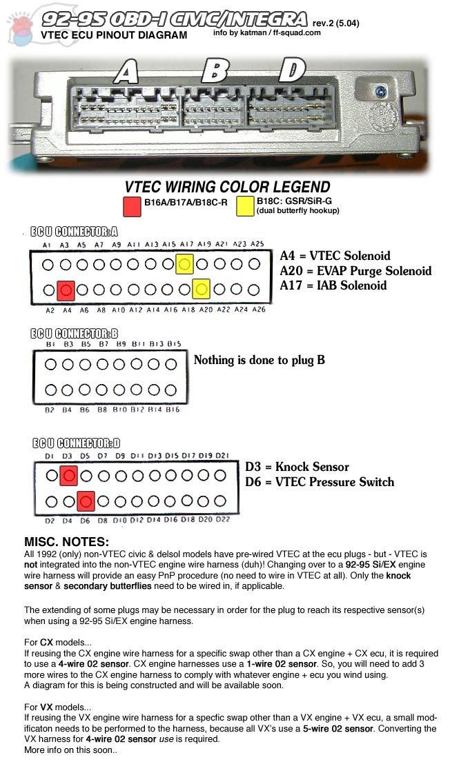
A1 BRN INJ1 INJ1Well it's a schematic of a p28 ecu. Vtec is a4, vtec oil pressure switch is d6
A2 YEL INJ4 INJ4
A3 RED INJ2 INJ2
A4 GRN/YEL VTS VTEC solenoid
A5 BLU INJ3 INJ3
A6 ORN/BLK PO2SHTC O2 sensor (heating element)
A7 GRN/BLU FLR1 fuel pump
A8 (empty)
A9 BLK/BLU IACV IAC valve
A10 (empty)
A11 (empty)
A12 GRN FANC engine coolant temp switch
A13 GRN/ORN MIL MIL (check engine light)
A14 (empty)
A15 BLK/RED ACC (a/c compressor clutch)
A16 WHT/GRN ALT C alternator
A17 PNK/BLU IAB IAB Solenoid
A18 (empty)
A19 YEL (AUTO ONLY) (a/t trans only)
A20 RED PCS EVAP purge control solenoid
A21 YEL/GRN ICM ICM
A22 (empty)
A23 BLK PG1 ground
A24 BLK PG2 ground
A25 YEL/BLK IGP2 to main relay and to gound for o
A26 BRN/BLK LG1 gound
B1 YEL/BLK IGP2 to pin A25
B2 BRN/BLK LG2 ground to shields for CYP & TDC
B3 (a/t trans only)
B4 (a/t trans only)
B5 BLU/RED ACS a/c switch
B6 (empty)
B7 (a/t trans only)
B8 GRN PSPSW PSP switch
B9 BLU/WHT STARTER SIGNAL starter signal
B10 ORN VSS vehicle speed sensor
B11 ORN CYP P CYP -P
B12 WHT CYP M CYP -M
B13 ORN/BLU TDC P TDC -P
B14 WHT/BLU TDC M TDC -M
B15 BLU/GRN CKP P CKP -P
B16 BLU/YEL CKP M CKP -M
D1 WHT/BLU VBU Back Up Power
D2 GRN/WHT BKSW brake switch
D3 KS Knock Sensor
D4 BRN/WHT SCS service check connector
D5 (empty)
D6 BLU/BLK VTM VTEC pressure switch
D7 LT BLU TXD/RXD (data link connector)
D8 (empty)
D9 WHT/RED ALT F alternator
D10 GRN/RED ELD electric load detector
D11 RED/BLK TPS TPS Signal
D12 YEL/GRN
D13 RED/WHT ECT ECT sensor
D14 WHT/RED PHO2S O2 sensor
D15 RED/YEL IAT IAT sensor
D16 WHT/BLK VREF VREF
D17 WHT/YEL MAP Map Signal
D18 (a/t trans only)
D19 YEL/WHT VCC1 MAP 5V
D20 YEL/BLU VCC2 TPS 5V
D21 GRN/WHT SG1 MAP GND
D22 GRN/BLU SG2 TPS GND


